


light industry
Application of ECF300 inverter in hot melt compounding machine
2016-05-13
一、preface
Composite machine is an important equipment in the packaging and printing industry, the so-called composite refers to the process by a certain way, the two or more than two kinds of materials together to form a new one,
After the composite material on the one hand to maintain the advantages of the original material, on the other hand, can make up for each other's shortcomings. The common methods include dry composite method, wet composite method and heat
Melt recovery method, extrusion method and solvent free composite method.
Composite hot melt machine is by thermal radiation hot-melt lamination processing of plastic, sheet, cloth, and so on, the two or more than two kinds of different materials combined with applying certain pressure to the composite
One of the processing machine, used for leather garment, shoe soles, light foam sheets and composite processing and its advantages in PE film is used instead of glue joint, product inventory time long, no change
Signs of color, not easy to tear, the effect is better than the adhesive bonding.
二、Composition and frequency conversion control of hot melt type composite machine
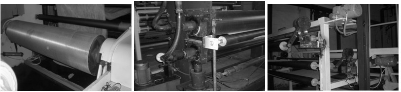
Hot melt compounding machine is generally composed of three parts, the volume, the hot press, and the volume. Below with a non-woven factory in Jiangyin engineering examples for illustration.
1, put the volume part
The unwinding part a total of three kinds of materials, in the middle of the two layers of non-woven fabrics clip a layer of hot melt adhesive film, using frequency converter ECF300 as the power line, the use of tension and back 0 ~ 10V
Signal and give quantitative signal for bidirectional PID arithmetic, PID given by an external potentiometer to achieve, which tension and weight by the pressure achieve in order to adapt to the requirements of the different materials of different tension. Roll off
In order to ensure that the material tension between the roll and hot roll is basically the same, otherwise it is easy to appear the fold of the material. At the same time, the feedback signal is used to ensure that the frequency converter is in the case of no material or material breakage.
Shut down.
2, hot compression part
Three layers of material on the line out after the formation of the hot compression roller. Hot compression roller is divided into two parts, the internal are high temperature hot compression oil, the height of the two rollers can be adjusted through the air pressure,
On the surface of the roller with dense and uniform distribution of needle shaped teeth is conducive to the material with a good fit. The heat compression roller is only the traction drive roller, and the ECF100/ECF300 can be used, the frequency is given by the external potentiometer,
Can be individually adjusted and can also be linked with the winding motor.
3, the volume part
In this project, the rolling friction is adopted, which is driven by a ECF100 inverter. The roll up roll is driven by the frictional force between the large rollers, and the switching between the two rollers.
Compacted present. The volume of this volume is not large, the distance between each part of the material is not long tensile strength is also very good. If the volume is large or the material tensile strength is not strong, please use ECF300 frequency conversion
Center roll up.
yichuangfei ECF300 inverter is a can realize the winding or unwinding process of the constant tension control of inverter. The actual diameter of the material can be obtained through the calculation of the frequency converter.
Frequency converter output torque to obtain constant tension control. Yi a fly inverter can be set through the system compensation of inertia, friction compensation and inertia compensation to compensate the system inertia, friction resistance
And the speed of the material in the process of starting or accelerating process is not uniform, and the result is very smooth. The scheme is simple and easy to debug. ECF300 can also be set by tension
Taper coefficient, so that the volume of the winding tension decreases with the increase of the volume diameter, and achieve the best effect of inner tight outer loose.
三、Parameter setting
|
Roll converter parameter setting |
|||||
|
Function code |
Function code name |
Set value |
Function code |
Function code name |
Set value |
|
F0.00 |
control mode |
1 |
F0.01 |
Speed torque control mode |
0 |
|
F0.02 |
Run command channel |
1 |
F0.03 |
Frequency given main channel |
8 |
|
F0.09 |
Maximum output frequency |
70.00 |
F0.11 |
Upper frequency digital setting |
70.00 |
|
F0.14 |
Acceleration time 1 |
1 |
F0.15 |
Deceleration time 1 |
1 |
|
F3.00 |
VS1 lower limit value |
实测 |
F3.02 |
VS1 Upper limit value |
actual measurement |
|
Fb.00 |
PID controller for a given signal source |
0 |
Fb.01 |
Keyboard digital PID given |
50% |
|
Fb.02 |
PID controller feedback signal source |
2 |
Fb.05 |
PID output characteristic selection |
1110 |
|
Fb.08 |
Proportional gain P1 |
1.06 |
Fb.09 |
Integration time I1 |
5 |
|
Fb.11 |
sampling period |
0.0 |
Fb.12 |
PID control deviation limit |
0% |
|
Fb.23 |
Proportional gain P2 |
1 |
Fb.24 |
Integration time I2 |
8 |
|
Fb.26 |
Second valid range of PID parameters |
15% |
|
|
|
Hot press parameters of the inverter is relatively simple, here is not to do a detailed introduction.
|
Winding converter parameter setting |
|||||
|
Function code |
Function code name |
Set value |
Function code |
Function code name |
Set value |
|
F0.00 |
control mode |
0 |
F0.01 |
Speed torque control mode |
1 |
|
F0.02 |
Run command channel |
1 |
F0.03 |
Frequency given main channel |
0 |
|
F0.09 |
Maximum output frequency |
50 |
F0.11 |
Upper frequency digital setting |
50 |
|
F0.17 |
Acceleration time 1 |
1 |
F0.18 |
Deceleration time 1 |
According to field settings |
|
F3.00 |
VS1 lower limit value |
actual measurement |
F3.02 |
VS1 upper limit value |
actual measurement |
|
F7.00 |
Torque given main channel |
0002 |
F7.01 |
Torque keyboard data set |
100% |
|
F7.06 |
Output torque limit |
100 |
F7.08 |
Torque compensation set selection |
1 |
|
F7.09 |
Torque taper coefficient |
20 |
F7.15 |
Static friction compensation |
5 |
|
F7.16 |
Sliding friction compensation |
5% |
F7.17 |
Moment of inertia compensation |
5 |
四、Concluding remarks
In the whole process through the outer connected potentiometer, acceleration and deceleration regulation is basically consistent tension. The drive roll can be real time according to the change of the tension adjust the speed of response
Quick, the tension roller always keeps in the center point, the material composite roll up effect is very good.