


light industry
A specific form of bobbins design rules for the implementation of control cable
2016-05-12
In the drawing and change pull, cable, such as rolling industry and is widely applied to accept wire, control, take-up in general is no wonder that the tension control line, torque take-up, constant linear velocity line. The two models are the main. Control strategy of take-up we discussed in another chapter, I will only on special rolling machine control to illustrate:
Cable current customers encounter difficult control technology generally includes the following:
1, precision winding
2, gradient line
3 and the taper winding
4, inclined cable
5, constant speed wire cable
Is the main line, precision control precision must be closely arranged, difficulties in the timely treatment of commutation. In the design concept, cable necessarily line push pushed line, line in advance the process to have a lag angle. This angle must be well controlled, if need to obtain good precision cable effect, then the constant tension active wire releasing is an indispensable link, only control the release of tension, in order to control the good precision winding lag angle position. Only control the walking wire feeding precision can be handy to lag angle, precision control cable. Roundwood line to achieve precision arrangement is relatively easy to implement, but if it is strip material, then it must be in commutation limit do the necessary auxiliary treatment, because of the strip line, no bottom surface of the semicircular, do not have the ability to automatically find the location of the. When the strip cable must be forced commutation position. Strip line is very easy to fold line, normal walking through row distance control to overcome a stacking line, reversing cannot as such, we can in a strip line arrangement of the starting point of sampling a signal origin, when the signal is effective, must be reversing the best time and can be pre setting a cylinder, cylinder stretching length equal to a strip of row spacing and the reversal forced origin reversal distance control is arranged strips of optimal control method.
Gradient cable, control a whole shape, trapezoidal wire arranging process, if need in the face of the shaft disk to achieve gradient cable, then it must be accurate control of row spacing, the so-called row spacing is between the lines and the cable line in the effective space distance is generally in order to improve the utilization efficiency, encourage ternary a cable model is the perimeter of each week rotation cycle over the point of maximum space distance must be 2 times the diameter of your cable material. In non precision cable, row spacing control is a very important control quantity, if the row distance control not to live, there is no way to to a good control of the other parameters. The design idea of specific design of control cable can be calculated by gradient realization.
On the gradient (taper) calculation principle of cable:
Can artificially set the gradient of high value. Set a high value: H
Can artificially set the diameter of wire. A wire diameter: diameter
Can be artificially set the length of the line of the line: L
The number of pulse length of the wire receiving disk through the system mechanical self learning: M
You can set the line of the artificial pitch is sparse, this value is very important in relation to the control precision. The general is a three, can also be fine row, is the line next to the line, there is no gap between the line and the line. If a is three, the control coefficient set "3" if it is fine for the "1 row set control coefficient".
The need to control the high gradient values: H divided by the wire diameter is equal to the number of the formation of the gradient line. H/ with =F
F*3= the actual needs of the gradient of the formation of layers, according to the wire is if you have a sparse pitch is 3, can be understood as two adjacent lines can also be sandwiched between the two lines, this is the pitch is equal to 3. If it is fine, it is equal to 1.
Take the take-up reel the total length of the pulse forming a divided by the number of gradient layers can be obtained round-trip virtual reversal distance of each layer of the cable. For example, the number of the total plate length is 12000. Wire diameter of 0.3 mm. The maximum height of the gradient is 10 mm. The calculation of the formation of the gradient of initial cable layer number is 10/0.3=33. So if the cable is sparse, you must row 3 layer can be converted into a line of height to diameter, the general cable is ternary calculation, if it is the essence of the platoon can not by this coefficient. A hypothesis is three, you need 99 lines to the formation of gradient layer.
The total length of the plate pulse number 12000 divided by gradient formed the basic number 99 is equal to every layer of the cable in a direction to another direction when walking round trip condition of commutation, 12000/99=121
The first layer from left to right traversing, when go to 121 pulse distance must be returned, the second layer of the cable from left to right traversing, when go to 242 pulse distance must return, and so on. When the 99th floor aisle 12000 pulse gradient cable is completed, is switched to the normal mode of cable. One end of the gradient is just higher than the other end of our set value of 10 mm.
When the gradient cable is completed, switching commutation conditions can not do impulse control, directly hit the limit signal return immediately. If the taper is to calculate the taper of the extension distance.
If need to control the receiving line constant speed, you need to calculate the roll diameter, that is in the initial roll diameter based on each row of a layer of wire, plate diameter increased 2 phi, then find out the plate around the perimeter of the fine line, set line velocity divided by the mechanical transmission ratio and divided by the motor pole pair number equal to the frequency of operation speed.
Then the design and calculation of inclined cable taper reference category can be calculated:
1 conical spool
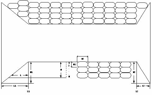
Any cone type spool and line diagram as shown above. Conical spool left length L1 and height H1; the right length L2, a height H2, irregular cable at the height of the D1, with a length of D2, round type cable
D1=D2=. S1 and S2 are the left and right limit switches, which can be used as mechanical reversing switches or electronic switches. After the winding machines hit the limit switch, do not immediately reverse, and according to the layers of the traversing machine speed, cable, wire line diameter and other parameters determine a delay time, the winding machines to the original direction of running the delay time after the reverse. Cable layer, different feeding speed is different, the delay time is different. Delay time is not a fixed value, but a constant value. Each hit a rolling machine limit switch S1 or S2, with 1 layers of N cable.
Rolling machine for each rotation of the screw displacement C (mm).
The rated frequency of rolling machine is Fe, synchronous speed (RPM / N0).
Rated frequency Fe= cable machine. N0= synchronous speed (RPM RPM / min).
The operating frequency of rolling machine is F, the operating frequency of the winding machine for F1. The linkage between the two is F=D2/C*F1.
The operating frequency of F= winding machine. D2= wire width, if the diameter of spar.
The displacement distance of the C= line machine rotates one week. Operating frequency of F1= wire winding motor.
The N layer cable hit the left limit switch is to move a distance M1=N*D1*L1/H1
Displacement distance of M1= after hitting the left limit switch. N= cable layer, which is limited to the number of hit.
D1= wire line height, spar diameter. L1= the total length of the left taper.
The total height of the left line taper H1=.
The N layer cable hit the right limit switch is to move a distance M2=N*D1*L2/H2
Displacement distance of M2= after hitting the right limit switch. N= cable layer, which hit the right limit the number of times.
D1= wire line height, spar diameter. L2= the total length of the right taper.
The total height of H2= right taper wire.
In order to ensure the cable in the cone of neat cable, M1, M2 as integer times of traversing width D2. Therefore, the actual use of M1, M2, rounding operation.
M1=[(N*D1*L1/H1) /D2]*D2 [] for mathematical rounding, is equal to 1, up less than 1.
M2=[(N*D1*L2/H2) /D2]*D2
Type: M1= left hit the limit after walking distance, N= cable layer, is also hit the limit number.
D1= wire line height, spar diameter. L1= the total length of the left taper distance.
H1= the total height of the left taper disc. D2= wire line width, spar diameter.
M2= right hit the limit after walking distance, N= cable layer, is also hit the limit number.
D1= wire line height, spar diameter. L2= the total length of the taper on the right.
H2= the total height of the taper disc on the right. D2= wire line width, spar diameter.
The distance M1 corresponds to the number of rotations of R1=M1/C rolling machine.
The rotating ring R1= traversing motor left hit the limit of the number of post. Running distance of M1= left collision limit.
C= cable cable motor displacement per week running distance.
The distance M2 corresponds to the number of rotations of R2=M2/C rolling machine.
The rotating ring R2= traversing motor right hit the limit of the number of post. M2= right hit limit running distance.
C= cable cable motor displacement per week running distance.
Rolling machine per minute rotating circle number E=F* N0/Fe.
Run around every minute of the E= motor cable number. The operating frequency of F= motor cable.
N0= synchronous speed. Rated frequency Fe= cable machine.
Rolling machine hit the left limit switch S1 to the left running time is T1=R1/E, in minutes. After the cable converter reverse cable, motor reversal, moves to the right, and 1 layers of cable.
S1= left limit switch. Continuous running time after T1= left line collision limit. (immediately after the end of the implementation of the change).
R1= cable hit left hit the limit after the number of rotating ring. Run around every minute of the E= motor cable number.
Rolling machine hit right limit switch S2 to continue to run the unit for minute time is T2=R2/E. After the cable converter reverse cable, motor reversal, left running, and 1 layers of cable.
S2= right limit switch. Continuous running time after the T2= right line is hit by a limit. (immediately after the end of the implementation of the change).
R2= cable hit right hit the limit after the number of rotating ring. Run around every minute of the E= motor cable number.
Maximum number of layers Nmax=[(H1-5~10) /D1]= [(H2-5~10) /D1]. When the maximum layer is reached or exceeded, the system is shut down and the volume change continues.
Maximum number of Nmax= layers. H1= the total height of the left taper disc. 5-10= safety factor.
D1= the height of the wire, round wire for its diameter. Continuous running time after T1= left line collision limit.
H2= the total height of the right taper disc.
T1=60*1000*[(N*D1*L1/H1) Fe/ /D2]*D2* (F* N0 C*) units in milliseconds.
Continuous running time after T1= left line collision limit. 60= conversion factor per second. 1000= conversion factor per millisecond.
Stacking layers of N= wire. D1= the height of the wire, round wire for its diameter.
L1= the total length of the left taper distance. H1= the total height of the left taper disc.
D2= the width of the wire, round wire for its diameter. Rated frequency Fe= cable machine.
C= cable cable motor displacement per week running distance. The operating frequency of F= motor cable.
N0= synchronous speed.
T2=60*1000*[(N*D1*L2/H2) Fe/ /D2]*D2* (F* N0 C*) units in milliseconds.
Continuous running time after the T2= right line is hit by a limit. 60= conversion factor per second. 1000= conversion factor per millisecond.
Stacking layers of N= wire. D1= the height of the wire, round wire for its diameter.
L2= the total length of the taper on the right. H2= the total height of the taper disc on the right.
D2= the width of the wire, round wire for its diameter. Rated frequency Fe= cable machine.
C= cable cable motor displacement per week running distance. The operating frequency of F= motor cable.
N0= synchronous speed.
In order to avoid traversing machine operating frequency is zero or too small causing T1, T2 arithmetic overflow, the set a minimum frequency Fmin and Fmin take 2~5Hz.
Fmin= minimum operating frequency. Running time after T1= left line collision.
Running time of T2= right after hitting limit.
T2, T1 must be converted into milliseconds to participate in PLC floating-point operations, PLC can not be the value after the decimal point.
T2, T1 only at run time, parameter setting and fault operation.
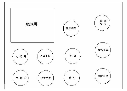
2 operating table
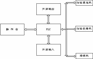
3 system diagram
4 touch screen display
4.1 boot screen
4.2 system status display
4.3 process parameters
4.4 line speed
4.5 product line weight (specific gravity, perimeter)
4.6 system fault display is preferred.
5 electrical connection point of each unit
5.1 operation panel
5.1.1 button switch
5.1.1.1 power supply - the system's total power switch, inverter, PLC, touch screen and other power supply.
5.1.1.2 power off - the total power off of the system.
5.1.1.3 start -- start drawing wire drawing inverter, transducer winding automatically follow the drawing wire drawing operation of the transducer, cable controller automatically follow transducer winding operation.
5.1.1.4 parking -- drawing drawing inverter parking, transducer winding, a winding machine with inverter automatically follow the drawing drawing inverter parking.
5.1.1.5 fault reset - after the failure of the inverter, the reset inverter fault, allowing the inverter to re run.
5.1.1.6 volume reduction -- conical spool wire with diameter, a new volume reduction, the number of N is set to 1.
5.1.2 self locking switch
3.1.2.1 emergency stop - the system is an emergency, the frequency converter free parking, winding up the inverter parking brake.
5.1.3 display
5.1.3.1 fault alarm indicator - frequency converter fault, sound and light alarm.
5.1.3.2 touch screen display - L1, H1, L2, H2, D1, D2, Fe, C, N0, Fmin, K (meter wheel circumference) set, working status, fault, etc..
5.1.4 potentiometer
5.1.4.1 speed potentiometer - line drawing machine speed, wire drawing inverter analog voltage given VS.
5.1.4.2 row spacing adjustment potentiometer to adjust the inverter speed of rolling machine, the different wire diameter basic cable closely. For the same line of the diameter of the cable, after adjustment, the potentiometer does not need to operate.
5.2 system input
5.2.1.1 left limit switch S1 - delay T1 after the time limit, to the right to run.
5.2.1.2 left limit switch S2 - after the delay T2 time limit, to the left.
5.2.1.3 FDT - 1HZ FDT converter cable cable effectively, to calculate T1, T2.
5.2.1.4 - the inverter fault drawing, winding, winding any inverter fault.
5.2.1.5 meter input - line length.
5.2.2 output
5.2.2.1 cable machine reversing - positive turn right, left for the reversal.
5.2.2.2 meters to the parking or parking trayful.
5.3 converter connection
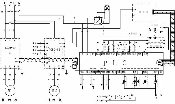
Roughly peripheral configuration needs: frequency converter, PLC, touch screen (text display), photoelectric rotary encoder, communication module.
Summary method:
To get anywhere in the cable precise control, must control non precision cable of row spacing, only control the row spacing, it may control cable need to control the arrangement, of course, precision cable is not necessary to row spacing to deliberately control. Because precision wire spacing and row has generated naturally, take-up reel length control.